After you have built your first 10 Mirth Connect channels, a pattern emerges: some channels are clean, maintainable, and easy to troubleshoot. Others are tangled messes of JavaScript, nested conditionals, and destination chains that nobody wants to touch. The difference is not experience or talent. It is architecture.
Channel design patterns are the difference between a Mirth deployment that scales to 50+ channels managed by a single engineer and one that collapses into an unmaintainable pile of spaghetti channels at 15. These five patterns, applied consistently, keep your integration architecture clean regardless of how many systems you connect.
This guide covers each pattern with complete code examples, shows when to use each one, and explains the anti-patterns that cause the most production incidents. If you have read our guide to building a robust HL7 interface engine and our backlog elimination playbook, this is the next level: moving from functional channels to well-architected channels.
Why Channel Architecture Matters
A poorly architected Mirth deployment exhibits predictable symptoms:
- One channel does too many things. A single channel receives ADT, ORM, and ORU messages, routes them based on complex conditionals, transforms them differently for each destination, and handles errors inline. When something breaks, finding the problem takes hours.
- Changes are risky. Modifying a transformer in a multi-purpose channel risks breaking other message flows. Engineers start avoiding changes, leading to workarounds layered on workarounds.
- Troubleshooting is slow. When a message fails, you cannot tell at a glance whether the problem is in the source, the routing logic, the transformation, or the destination. Every investigation starts from scratch.
- Scaling is manual. Adding a new destination system means modifying existing channels instead of deploying new ones. The blast radius of every change grows with the number of destinations.
Good architecture solves all of these by applying a simple principle: each channel should do one thing well. The five patterns below are specific implementations of this principle for common healthcare integration scenarios.
Pattern 1: Fan-Out (One Source, Many Destinations)
The most common pattern in hospital integration. A single source system (usually the HIS) sends messages that need to reach multiple downstream systems.
When to Use
ADT distribution is the canonical example. When a patient is admitted (A01), the event needs to reach the lab system, radiology, pharmacy, billing, bed management, dietary, and possibly a dozen other systems. Each destination needs a slightly different subset of the data, potentially in a different format.
Implementation
Channel: ADT_FANOUT
Source: TCP Listener (Port 6661, MLLP)

Destination 1: Lab System
  Connector: TCP Sender (10.0.1.50:7001)
  Filter: Pass A01, A02, A03, A04, A08 only
  Transformer: Map to lab-specific format

Destination 2: Radiology
  Connector: TCP Sender (10.0.1.60:7002)
  Filter: Pass A01, A03, A04, A08 only (no transfers)
  Transformer: Map to radiology format, add Z-segment

Destination 3: Pharmacy
  Connector: TCP Sender (10.0.1.70:7003)
  Filter: Pass A01, A02, A03, A04 only
  Transformer: Include medication allergy data from AL1 segment

Destination 4: Billing
  Connector: TCP Sender (10.0.1.80:7004)
  Filter: Pass A01, A03 only (admit and discharge)
  Transformer: Map insurance data from IN1/IN2 segments

Each destination has:
  - Its own filter (processes only relevant events)
  - Its own transformer (maps to destination format)
  - Its own queue (independent retry and error handling)
  - Queue enabled: Yes, Retry: 5 attempts, 30s interval
Key Design Rules
- Independent queuing per destination. If the pharmacy system goes down, lab results still flow. Each destination queue operates independently.
- Destination-specific filters. Not every destination needs every event type. Apply filters at the destination level, not the source level. This makes it clear which events each system receives.
- No shared state between destinations. Do not use channel maps to pass data between destinations. Each destination transformer should be self-contained.
Pattern 2: Aggregation (Many Sources, One Destination)
When to Use
Multiple departmental systems send results to the EHR. The lab LIS, the radiology RIS, the cardiology system, and the pathology system all produce ORU messages that need to flow into the central EHR. Each source has a slightly different message format, different field mappings, and different quirks.
Implementation
// Option A: One channel per source (RECOMMENDED)
Channel: ORU_LAB_TO_EHR      (Source: Lab LIS, Port 6671)
Channel: ORU_RAD_TO_EHR      (Source: Radiology RIS, Port 6672)
Channel: ORU_CARDIO_TO_EHR   (Source: Cardiology, Port 6673)
Channel: ORU_PATH_TO_EHR     (Source: Pathology, Port 6674)

Each channel:
  - Source transformer: Normalize to standard ORU format
  - Destination: Same EHR endpoint (10.0.2.10:8001)
  - Each channel handles source-specific quirks independently

// Option B: Single channel, multiple source connectors (simpler but less isolation)
Channel: ORU_ALL_TO_EHR
  Source 1: TCP Listener Port 6671 (Lab)
  Source 2: TCP Listener Port 6672 (Radiology)
  Source transformer: Detect source, apply appropriate normalization
  Destination: EHR endpoint
Why Option A is Better
Option A (separate channels per source) is preferred because:
- Each source has independent error handling. A problem with the radiology interface does not affect lab results.
- Source-specific transformations are isolated. Modifying the cardiology mapping does not risk breaking the lab mapping.
- Monitoring is granular. You can see message counts and error rates per source system.
- Deployment is independent. Updating one channel does not redeploy others.
Pattern 3: Content-Based Router
A single feed contains multiple message types that need different processing. Instead of building complex conditionals in one channel, route each message type to a specialized processing channel.
Implementation
Channel: MSG_ROUTER (receives all HL7 from HIS)
  Source: TCP Listener (Port 6660)
  Source Transformer: Extract routing key

  // Source transformer code:
  var msgType = msg['MSH']['MSH.9']['MSH.9.1'].toString();
  var triggerEvent = msg['MSH']['MSH.9']['MSH.9.2'].toString();
  channelMap.put('msgType', msgType);
  channelMap.put('routingKey', msgType + '_' + triggerEvent);

  Destination 1: ADT Processing
    Filter: $('msgType') == 'ADT'
    Connector: Channel Writer -> ADT_PROCESSING channel

  Destination 2: Order Processing
    Filter: $('msgType') == 'ORM'
    Connector: Channel Writer -> ORM_PROCESSING channel

  Destination 3: Results Processing
    Filter: $('msgType') == 'ORU'
    Connector: Channel Writer -> ORU_PROCESSING channel

  Destination 4: Financial Processing
    Filter: $('msgType') == 'DFT' || $('msgType') == 'BAR'
    Connector: Channel Writer -> FIN_PROCESSING channel

  Destination 5: Unrouted Messages
    Filter: Default (catches everything not matched above)
    Connector: Channel Writer -> UNROUTED_ERROR channel
The Critical Detail: Catch-All Destination
Always include an "unrouted" destination that catches message types you have not explicitly handled. Without this, a new message type from the source system (say, MFN master file notifications) will be silently dropped. The unrouted channel logs these messages and alerts the integration team that a new message type needs handling.
Pattern 4: Transformation Pipeline
When to Use
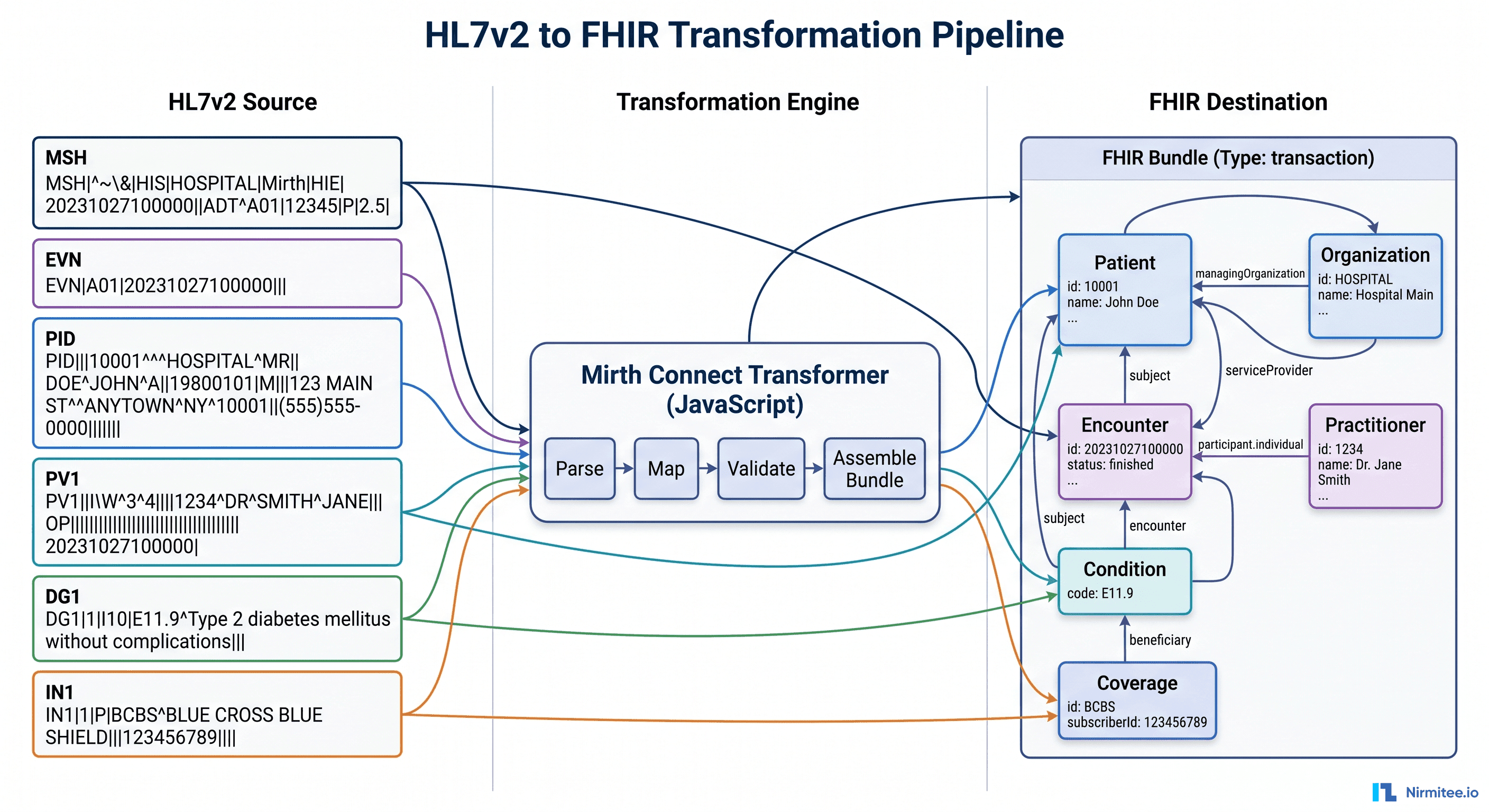
Complex transformations that are better broken into sequential steps than packed into a single monolithic transformer. This is common when converting HL7v2 to FHIR or when multiple enrichment steps are needed (lookup patient in MPI, fetch insurance from payer database, validate against formulary).
Implementation
// Pipeline: HL7v2 ADT -> Enriched FHIR Patient Resource

Channel 1: ADT_RECEIVE
  Source: TCP Listener (MLLP)
  Transformer: Basic validation, extract MRN
  Destination: Channel Writer -> ADT_ENRICH

Channel 2: ADT_ENRICH
  Source: Channel Reader
  Transformer:
    Step 1: Lookup patient in Master Patient Index (MPI)
    Step 2: Fetch active insurance from coverage database
    Step 3: Check for existing FHIR Patient resource
  Destination: Channel Writer -> ADT_TRANSFORM

Channel 3: ADT_TRANSFORM
  Source: Channel Reader
  Transformer: Convert enriched HL7v2 + MPI data -> FHIR Patient Bundle
  Destination: HTTP Sender -> FHIR Server PUT /Patient

// Each channel does ONE thing:
// Channel 1: Receive and validate
// Channel 2: Enrich with external data
// Channel 3: Transform format and deliver
When NOT to Use a Pipeline
Simple field-to-field mappings do not need a pipeline. If your transformation is "copy PID.5 to patient_name and PV1.3 to location," put it in a single channel transformer. Pipelines add latency (each channel handoff has overhead) and complexity. Use them only when the transformation genuinely has distinct logical stages.
Pattern 5: Dedicated Error Handling Channel
This is not optional. Every production Mirth deployment needs a structured error handling pattern. The most common Mirth integration failure is messages that fail silently because error handling was an afterthought.
Implementation
Channel: ERROR_HANDLER (dedicated error processing channel)
  Source: Channel Reader (receives errors from all channels)

  Source Transformer:
    // Extract error context
    var sourceChannel = sourceMap.get('channelName');
    var errorMessage = sourceMap.get('errorMessage');
    var originalMessage = connectorMessage.getRawData();
    var errorTimestamp = new Date().toISOString();

    channelMap.put('sourceChannel', sourceChannel);
    channelMap.put('errorMessage', errorMessage);
    channelMap.put('errorTimestamp', errorTimestamp);

  Destination 1: Error Database
    Connector: Database Writer
    SQL: INSERT INTO integration_errors
         (channel_name, error_message, original_message,
          error_timestamp, retry_count, status)
         VALUES ($('sourceChannel'), $('errorMessage'),
                 messageContent, $('errorTimestamp'), 0, 'NEW')

  Destination 2: Alert Notification
    Connector: HTTP Sender (Slack/Teams webhook or email API)
    Filter: Only for critical channels (ICU, Lab, Pharmacy)
    Body: Channel $('sourceChannel') error at $('errorTimestamp'):
          $('errorMessage')

  Destination 3: Retry Queue
    Connector: Channel Writer -> Original channel (for retryable errors)
    Filter: Error is transient (connection timeout, destination unavailable)
    Transformer: Increment retry count, check max retries (5)
    // If max retries exceeded, update DB status to 'DEAD_LETTER'
Connecting Channels to the Error Handler
In each production channel, configure the error handling to route to the ERROR_HANDLER channel:
// In each channel's source/destination error settings:
Error Channel: ERROR_HANDLER
Include: Error message, original message content, channel name

// In destination settings:
On Error: Queue message (do not discard)
Retry Count: 3 (before sending to error channel)
Retry Interval: 30000 ms
Combining Patterns: A Real-World Architecture
In practice, most hospital integrations combine multiple patterns. Here is how a typical 300-bed hospital's Mirth architecture looks:
TIER 1: Intake (Content-Based Router)
  MSG_ROUTER_HIS    - Routes all HIS messages by type
  MSG_ROUTER_LAB    - Routes all lab messages by type
  MSG_ROUTER_RAD    - Routes all radiology messages by type

TIER 2: Processing (Fan-Out + Transformation)
  ADT_FANOUT        - Distributes ADT to all subscribers
  ORM_LAB           - Orders from HIS to Lab (with enrichment)
  ORM_RAD           - Orders from HIS to Radiology (with enrichment)
  ORU_LAB_TO_HIS    - Lab results back to HIS
  ORU_RAD_TO_HIS    - Radiology results back to HIS

TIER 3: Specialty (Transformation Pipeline)
  FHIR_BRIDGE       - HL7v2 to FHIR conversion pipeline
  ABDM_GATEWAY      - ABDM integration channel

TIER 4: Infrastructure (Error Handling)
  ERROR_HANDLER     - Central error processing
  MONITORING        - Channel statistics collection
  AUDIT_LOG         - PHI access audit trail

Channel Groups:
  Group: Critical (ADT_FANOUT, ORU_LAB, ORU_RAD) - highest priority
  Group: Orders (ORM_LAB, ORM_RAD) - high priority
  Group: Financial (DFT, BAR channels) - normal priority
  Group: Infrastructure (ERROR_HANDLER, MONITORING) - always running
Channel Naming Conventions
A consistent naming convention makes 50+ channels manageable:
Format: MSGTYPE_SOURCE_TO_DEST or FUNCTION_SCOPE

Examples:
  ADT_HIS_TO_LAB         - ADT messages from HIS to Lab
  ORU_LAB_TO_HIS         - Results from Lab to HIS
  ORM_HIS_TO_RAD         - Orders from HIS to Radiology
  ADT_FANOUT             - ADT distribution to all systems
  MSG_ROUTER_HIS         - Message type router for HIS feed
  ERROR_HANDLER          - Central error processing
  FHIR_BRIDGE_ADT        - HL7v2 ADT to FHIR conversion

Anti-patterns:
  Channel1, Channel2     - Meaningless names
  Test_Channel           - Test channels in production
  HIS_Integration        - Too vague (what message type? what destination?)
Design Anti-Patterns to Avoid
Anti-Pattern 1: The God Channel
A single channel that receives all message types, contains hundreds of lines of JavaScript in the transformer, and sends to 10+ destinations with complex conditional logic. When this channel has a problem, everything breaks. Split it using the Content-Based Router pattern.
Anti-Pattern 2: Daisy-Chaining Without Purpose
Channel A sends to Channel B sends to Channel C sends to Channel D, where each channel does minimal processing. This adds latency and makes debugging difficult. Use pipelines only when each stage has a genuinely distinct purpose. If three channels together do what one channel could do with a slightly longer transformer, use one channel.
Anti-Pattern 3: Inline Database Queries in Transformers
Executing SQL queries inside transformer JavaScript is fragile and slow. If a lookup table is needed (mapping department codes, translating physician IDs), load the lookup table into a channel deploy script and store it in the global map. Access it from the transformer via globalMap.get('deptCodeMap'). This executes the query once at deploy time instead of once per message.
Anti-Pattern 4: No Source Filters
Processing every incoming message and then discarding it in the transformer wastes CPU cycles. If a destination only needs A01 and A03 events, add a destination filter that rejects everything else before the transformer runs. Filters are evaluated before transformers and are much lighter-weight.
Anti-Pattern 5: Copy-Paste Channel Duplication
When you need a similar channel for a different system, do not copy-paste and modify. Use Code Template Libraries for shared transformation functions and Channel Tags for organizing related channels. If 10 channels all use the same date formatting function, put it in a code template library. When you fix a bug in the function, all 10 channels benefit automatically.
Frequently Asked Questions
How many channels are too many?
There is no hard limit, but manageability is the constraint. A well-organized Mirth instance with consistent naming, channel groups, and shared code templates can manage 100+ channels. A poorly organized instance becomes unmanageable at 20. The architecture matters more than the count. If you are approaching 50+ channels, ensure you have proper monitoring and operational runbooks.
Should I use Channel Writer or TCP for inter-channel communication?
Use Channel Writer (channel-to-channel connector) for internal routing. It is faster than TCP (no network overhead), maintains message metadata across channels, and is easier to configure. Use TCP only when the downstream channel might run on a different Mirth instance in a clustered deployment.
How do I handle message ordering?
HL7v2 messages often need to be processed in order (an A01 admit before an A03 discharge for the same patient). Within a single channel, Mirth processes messages in order by default. Across channels (via router -> processing channel), order is preserved if source and destination queues use a single thread. If you enable multi-threaded processing, order is not guaranteed. For order-sensitive flows, keep the thread count at 1 for the relevant channels.
Can I version-control Mirth channels?
Yes, and you should. Export channels as XML and store in Git. Tools like MirthSync automate this by pulling channel definitions from the Mirth API and committing to a Git repository. This enables code review for channel changes, rollback to previous versions, and promotion across environments (dev -> test -> prod). See our upcoming guide on automated testing for Mirth channels for the full CI/CD approach.
The Bottom Line
Channel design patterns are not academic exercises. They are the practical foundation of every Mirth deployment that survives past the first year. The five patterns — fan-out, aggregation, content-based router, transformation pipeline, and dedicated error handling — cover the vast majority of healthcare integration scenarios.
Apply them consistently: one channel per concern, clear naming conventions, independent error handling, and shared code templates for common logic. The result is a Mirth deployment that a new engineer can understand in a day, that handles failures gracefully, and that scales to new systems by adding channels rather than modifying existing ones.
Start with the Content-Based Router for your main HIS feed. Add Fan-Out for ADT distribution. Build the Error Handler before your first production deployment.
These three patterns alone will cover 80% of your integration needs. The remaining 20% — aggregation and pipelines — add as specific requirements demand them.
Related guides
This article is part of our complete guide to Mirth Connect: What Is Mirth Connect? Complete 2026 Guide for Healthcare Leaders. Related deep-dives:
- Mirth Connect HL7 Interface Engine: Production Deployment Guide
- Healthcare Integration Architecture with Mirth Connect and Apache Kafka
- Managing 100+ Mirth Channels Without Losing Your Mind
- 5 Myths About Mirth Connect That Cost Health Systems Millions
Need production-grade Mirth Connect help? See our Mirth Connect integration services.